Create your own 3D Lego superhero
Meet Creative Bloq's own Lego superhero! With the Lego Movie out today, Pat Imrie explains how to model your own Lego mini-figure.

As we're sure you know by now, we're huge fans of Lego art here at Creative Bloq. So you can imagine our excitement at the release of the much anticipated Lego Movie in cinemas.
To celebrate the film's release, we asked digital artist Pat Imrie to create this awesome CB superhero Lego mini-figure. And now you design one too with his brilliant step-by-step guide on how to create your own 3D Lego character.
This guide was created using Maya, but any 3D software can be used including free software such as Blender (head here for some Blender tutorials to get you started). So let's dive straight in and start Lego modelling...
01. Collecting and setting up reference

For anyone looking to create their own 3D Lego mini-figure, there's an abundance of reference material available - a quick web search will get you everything you need. I found very accurate blueprints, which I set up as front and side reference images. I also collected other reference images of various mini-figures from different angles to help me add in details where required.
02. Modelling the Head
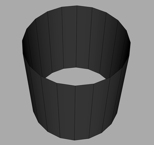
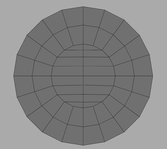
Primitives and bevels will be the most common elements to creating our Lego mini-figure. Starting with the head, create a Polygon cylinder with 12 sides and delete the caps off the top and bottom. Then fill in the caps with cleaner, quad-faced topology.
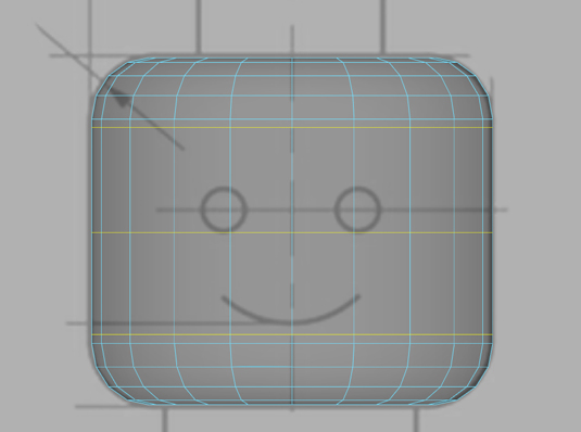
Now match the cylinder with the reference images and apply a rounded bevel to the top and bottom edges. Add in a few edge loops around the head to support the smoothness of the bevel. If the bevel doesn't match exactly we can edit the vertices to have it match more closely.
Finally select the faces on the top and bottom of our head and extrude these faces out to create the geometry for the top peg of the head and the neck.
Daily design news, reviews, how-tos and more, as picked by the editors.
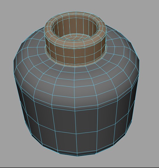
Bevel the edges to smooth them off before adding in a few edge-loops to clean up the geometry.
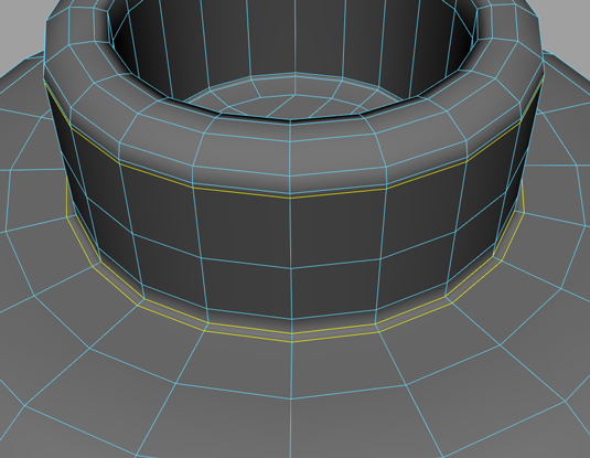
03. Modelling the body and hips
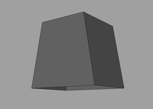
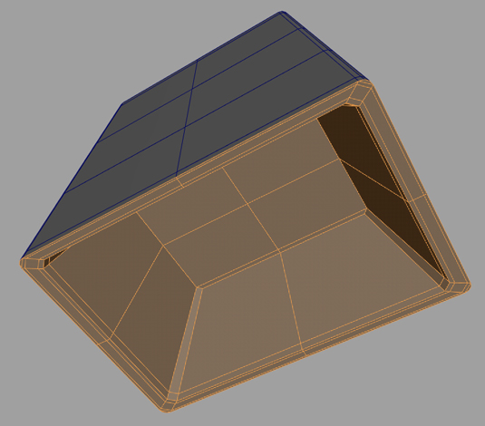
Starting with a cube we will delete the bottom face and then scale the top vertices in to create a trapezoid shape. Then we will select all but the bottom set of edges and apply a rounded bevel to them to create the desired look.
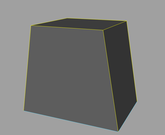
Before adding in new edge loops to help refine the shape and support the newly created bevels.
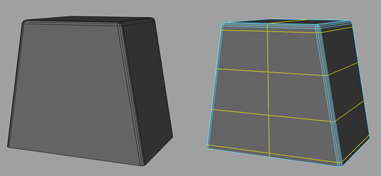
Next we will extrude the base in to create a recess for where the legs would go.
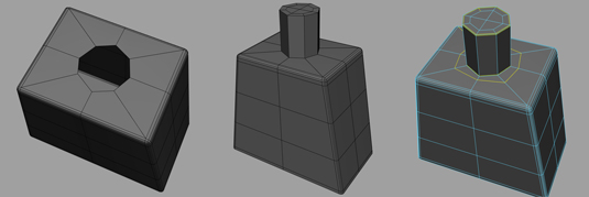
Next, select the vertex on the top of the body. Split or Chamfer this vertex and add in new edge loops to create a circular hole. Now select the edges and extrude up to create a neck peg, lastly cap off the hole and add in edge-loops to clean up the mesh.
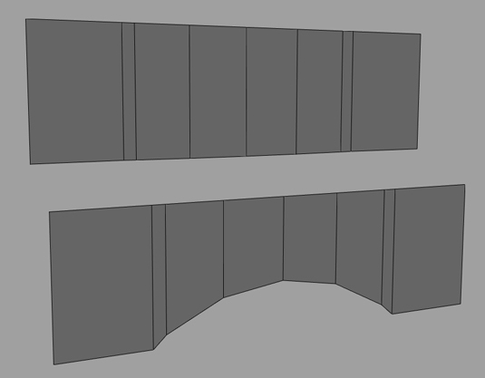
For the hips start with a polygon plane, eight divisions wide and adjust the shape into an archway.
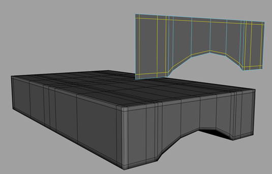
We will then add in new edge loops to support the shape before extruding the faces outward to create the hips.
Finally, create a cylinder with 12 sides and clean up the cap geometry as we did before and scale it down to match our hip geometry.
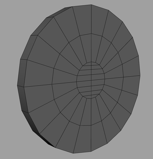
Then select the top eight faces and extrude them up and flatten them out to create the centre of the hips, adding edge loops where appropriate to cleanup and finalise the geometry.

04. Modelling the arm and hand
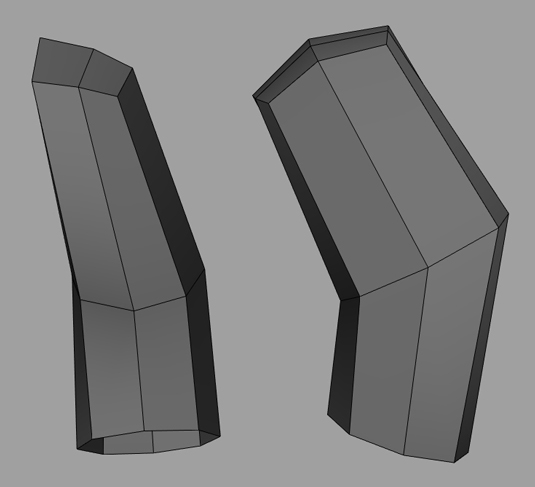
Starting with an eight-sided cylinder delete the caps and line up and reshape the cylinder with the forearm reference. Now extrude the edges up to create the upper arm and reshape as required. Now add in more edge loops to give us more geometry to further refine the shape of the arm.
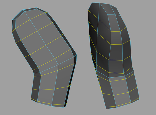
Lastly, select the edges around the wrist area and extrude them up to create a recess for the hand. Finishing the wrist off by bevelling and adding edge-loops to clean up the geometry.
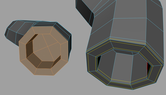
For the hand we will start with a 10-sided cylinder and delete the caps. Then delete the two underside faces.
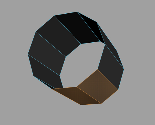
Reshape the hand based on the side reference before selecting all the faces and extruding them inwards to create thickness.
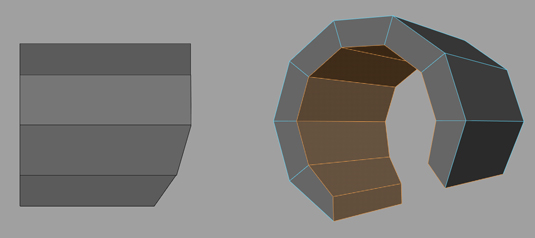
To complete the hand we will first add in some support edge loops and then split one of the top vertices so that we can extrude out the wrist of the hand.
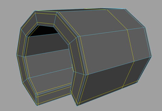
Finish the hand off by adding in some edge-loops to clean up the final mesh.

05. Modelling the leg
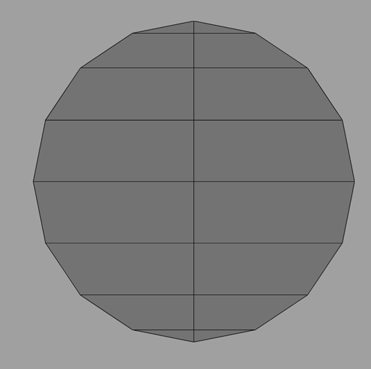
For the leg we start with a 16-sided cylinder and delete all but one cap, adjust the topology as in image above. Now select four faces on the underside and extrude them downwards, before adjusting the topology to create the shape seen below.
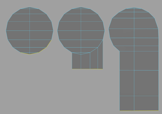
Create the foot by extruding out a bottom edge, then add in a border edge around the leg shape to help create clean topology later on.
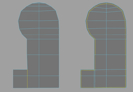
Next select all the faces of the leg shape and extrude them to create thickness of the leg.
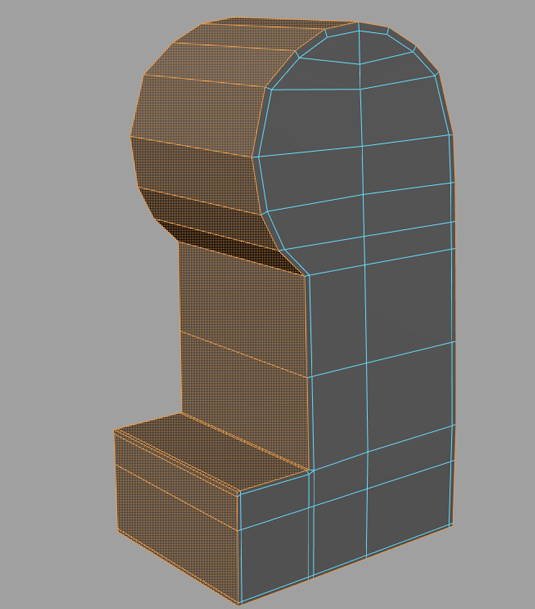
Then add in some supporting edge loops so that we can create the holes at the back of the legs.
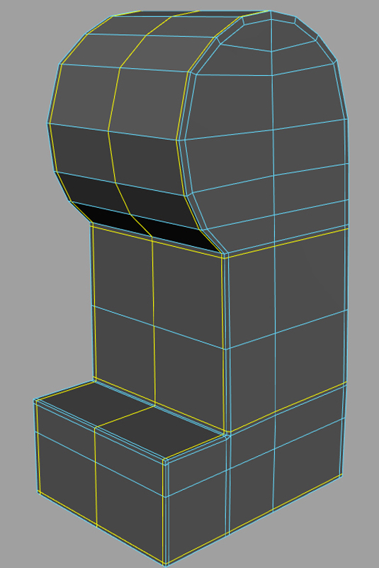
To create the holes we will split a vertex on the back of the leg and add in additional edge loops to create an eight-sided hole.
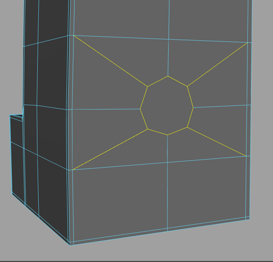
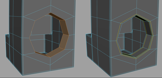
Now extrude edges in to create the finished hole, and repeat the process for the top hole, adding in edge-loops where required to finish off the leg geometry.
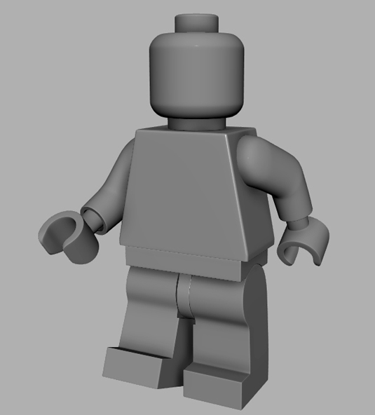
You now have your very own 3D version of a Lego mini-figure, which you can model accessories for and texture however you see fit.
Words: Pat Imrie
Pat Imrie is a freelance 3D artist and trainer specialising in modelling and digital sculpture for TV, film and games.
Liked this? Read these!
- Maya tutorials: 40 awesome projects to try today
- The best 3D movies of 2014
- Download free textures: high resolution and ready to use now
What should our Lego superhero be called? Give us your suggestions in the comments!

The Creative Bloq team is made up of a group of art and design enthusiasts, and has changed and evolved since Creative Bloq began back in 2012. The current website team consists of eight full-time members of staff: Editor Georgia Coggan, Deputy Editor Rosie Hilder, Ecommerce Editor Beren Neale, Senior News Editor Daniel Piper, Editor, Digital Art and 3D Ian Dean, Tech Reviews Editor Erlingur Einarsson, Ecommerce Writer Beth Nicholls and Staff Writer Natalie Fear, as well as a roster of freelancers from around the world. The ImagineFX magazine team also pitch in, ensuring that content from leading digital art publication ImagineFX is represented on Creative Bloq.
