Create amazing WebGL effects with shaders
Bartek Drozdz explains how to create stunning WebGL effects with shaders and his open source WebGL engine, J3D. You will build a lit, textured monkey head and the light should change its position as you move the mouse
WebGL lets you create stunning visual effects and animations in your browser without any plug-ins, the only thing you need is some JavaScript. True? Almost.
In fact, the magic effects created with WebGL that you have seen around the web owe much less to JavaScript and much more to the mysterious little programs called shaders and the language they are written with - called GLSL. In this tutorial, we'll take a closer look at what it is.
If you are new to WebGL, before you start this tutorial I suggest you to take a look at "Get started with WebGL: draw a square" first - it explains all the necessary basics.
Shaders are an integral part of WebGL. They are at the heart of the technology, and it's inside shaders that all the magic happens. For this tutorial we will be using a WebGL engine I wrote, called J3D that greatly facilitates shader development. Thanks to J3D we'll keep the WebGL/JS biolerplate code at a minimum and we will be able to load files containing GLSL code – something that is missing in WebGL by default.
Most WebGL tutorials, including my previous one use a <script> tag to embed shader code. This is a good technique for simple shaders. As soon as you need to write more code, the shortcomings of this technique become obvious – you need to include the code in your HTML document, you can't move it to an external file, there is no syntax colouring and the code can be difficult to read.
Setting up the environment
Before we delve into writing shader code, we need to setup our environment. First of all, since in J3D shaders are loaded using XMLHttpRequest, you will need to test your code using a server rather than using the file protocol. You can either upload the files to a external server or install one on your machine. If you choose the latter, MAMP is a very good option to consider.
HTML and JavaScript setup
Create an empty HMTL file. Place it on your web server in the folder of your choice and copy the files folder from the assets in the same folder. The files folder should include monkey.json, rock.png and j3d.js files.
Daily design news, reviews, how-tos and more, as picked by the editors.
We can now start editing the HTML file. The basic structure looks like this:
<!DOCTYPE html> <html> <head> <title>WebGL Shaders Tutorial</title> <script type="text/javascript" src="files/j3d.js"></script> <script type="text/javascript"> // code goes here </script> </head> <body> <canvas id="tutorial" width="960" height="640"/> </body> </html>Nothing complicated in here. In the head section, import j3d.js that contains the engine code. The body is composed of one single canvas element, that we will be using to render the 3D scene to.
Now time for some JavaScript. Inside the <script> tag insert the following code:
window.onload = function(){ engine = new J3D.Engine( document.getElementById("tutorial") ); J3D.Loader.loadGLSL("HemisphereLight.glsl", setup);}When the document is loaded, this function creates and instance of J3D – the engine. The next line invokes a function of the J3D.Loader object to load the file with the shader code: HemisphereLight.glsl. Once the file contents are loaded, the setup function is invoked. This function is where we build our scene and start rendering:
function setup(s){ monkey = new J3D.Transform(); monkey.renderer = s; J3D.Loader.loadJSON("files/monkey.json", function(j) { monkey.geometry = new J3D.Mesh(j); } ); camera = new J3D.Transform(); camera.camera = new J3D.Camera(); camera.position.z = 5; engine.camera = camera; engine.scene.add(monkey, camera); document.onmousemove = onMouseMove; draw();}This code creates a basic scene with J3D. First, we define a J3D.Transform called monkey. It's the basic building block of J3D scenes and it represents an empty object is the 3D space.
In order to get a more in depth introduction to J3D, please refer to this tutorial.
To become a shape visible in the scene, a transform needs two things: a renderer and a geometry. This is what the next two lines do. First we assing a renderer to the transform using the object passed as argument to the setup function. This argument is an object of type J3D.Shader that the loader created for us based on the GLSL file we loaded.
Next we use the loadJSON function to load the geometry. Geomtery is the data that defines the shape of the 3D object. Once it is loaded, using a scheme similar to that of loading GLSL, we assign and object of type J3D.Mesh to the transforms geometry property.
Take a look inside the monkey.json file to see what is part of the geometry definition. You'll see that the mesh has vertex positions, texture coordinates and normals. This is all we need for this tutorial, but J3D supports some more attributes like vertex colours or a secondary set of texture coordinates. To get your own 3D models you can either write an exporter script in a 3D editor, like Blender, that matches this format or use the Unity3D exporter that is part of J3D.
Next, we create a camera transform and add both transforms to the scene. Our scene is ready to be rendered now.
The final bits of code we need to add are below.
function onMouseMove(e) { mx = ( e.clientX / window.innerWidth ) * 2 - 1; my = ( e.clientY / window.innerHeight ) * 2 - 1;}function draw() { monkey.rotation.y += J3D.Time.deltaTime / 6000; engine.render(); requestAnimationFrame(draw);}The first function is a siple event listener for mouse move action. Whenever the mouse moves it sets two values – mx and my. We will later use them to animate some properties of the shader. The function draw is the rendering loop. At each frame we will rotate the monkey a bit.
Before we start creating our own shader, you can test if the JavaScript code so far works fine.
In order to do this, replace the line:
J3D.Loader.loadGLSL("HemisphereLight.glsl", setup);with
setup( J3D.BuiltinShaders.fetch("Normal2Color") );That way we skip the step where the external GLSL file is loaded, and use a J3D built-in shader, called Normal2Color to render the object. If everything goes well, you should see the monkey in nice rainbow colours! Make sure to roll back to the previous version before we continue.
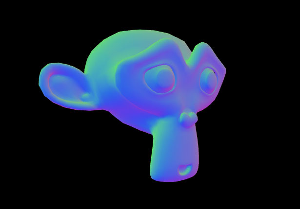
Once the HTML and JavaScript are in place we can finally move to the essence of this tutorial – writing the shader!
Shaders in J3D
Before we start typing any code, let's introduce some basic notions of shaders and see some J3D-specific features.
If you haven't done it yet, please take a look at the basic WebGL tutorial to learn shader basics first.
Like any other programming language GLSL, code can contain comments. Same as in JavaScript comment lines start with a double slash. J3D uses special comment lines, starting with //#, to add some necessary metadata. The basic structure of a shader is as follows:
//#name YourShaderNamecode common to both vertex and fragment shaders//#vertexdeclarationsmain vertex shader function//#fragmentdeclarationsmain fragment shader functionThe name declaration must be the first line of the shader. The name is a string with no spaces and it must be unique in your application. After the name declaration you can add code that is common to both vertex and fragment shaders.
The vertex shader comes after the line //#vertex. Typically it will start with a declaration of attribute, uniform and varying variables, followed by the shader main function.
After the vertex shader comes the fragment shader preceded by the line //#fragment. It's structure is similar to the vertex shader. First come the uniform and varying variables, then the main fragment function.
J3D will help you by providing data for some attributes and uniforms if you declare them. If J3D encounters an attribute or uniform variable with a specific name and type it will populate it with appropriate data. Here's the list of some common built-in attributes and uniforms:
- attribute vec3 aVertexPosition the position of the vertex
- attribute vec3 aVertexNormal the normal of the vertex
- attribute vec2 aTextureCoord the uv/texture coordinate of the vertex
- uniform mat4 mMatrix the model matrix, transforms vectors from local to world space
- uniform mat4 nMatrix the normal matrix, transforms normals from local to world space
- uniform mat4 vMatrix the view matrix, transforms from world to camera (view) space
- uniform mat4 pMatrix the projection matrix, applies perspective projection to 3d coordinates
Any shader that works with meshes in 3D space will most likely use most, if not all of them.
Creating a basic shader
Ready for some coding? Good! Create a file called HemisphereLight.glsl and place it in the same folder as your HTML file. Open the file in your editor and type in the following code:
//#name HemisphereLight#ifdef GL_ESprecision highp float;#endif//#vertexattribute vec3 aVertexPosition;uniform mat4 mMatrix;uniform mat4 vMatrix;uniform mat4 pMatrix;void main(void) { gl_Position = pMatrix * vMatrix * mMatrix * vec4(aVertexPosition, 1.0);}//#fragmentvoid main(void) { gl_FragColor = vec4(1.0, 0.0, 0.0, 1.0);}If you use Eclipse (Aptana) take a look at this plug-in that enables syntax colouring for GLSL files. For TextMate fans, there's a GLSL bundle as well.
It's a fairly simple shader to start with, but has all the crucial elements that we will need later on. First of all it declares the precision of the floats. It is a necessary boilerplate code to include in every shader – vertex and fragment alike. We keep it the common section after the //#name declaration, so that we don't have to write it twice.
The vertex shader declares one attribute and three uniforms – all of them are built-in. Inside the main function we transform the vertex. To understand the order of the operations it's best to read this line in reverse:
gl_Position = pMatrix * vMatrix * mMatrix * vec4(aVertexPosition, 1.0);First we add the homogenous coordinate to the vertex, making it a four component vector. Next we transform it from local space, in which it is declared, into world space by multiplying it by mMatrix. Next, the vMatrix transforms the point from world to camera coordinates and finally pMatrix applies the perspective projection. The vertex transformed like this can be passed to the GPU for rendering, so we assign it to the special variable called gl_Position which is the shaders way to return a value.
The fragment shader is even simpler. It just returns the same plain red colour for every pixel that is rendered. The effect of this shader is not very spectacular, but if your code runs fine you should now see something like this:

Adding a texture
To make the model look a bit better, let's replace the flat red colour with a texture:
//#name HemisphereLight#ifdef GL_ESprecision highp float;#endif//#vertexattribute vec3 aVertexPosition;attribute vec2 aTextureCoord;uniform mat4 mMatrix;uniform mat4 vMatrix;uniform mat4 pMatrix;varying vec2 vTextureCoord;void main(void) { vTextureCoord = aTextureCoord; gl_Position = pMatrix * vMatrix * mMatrix * vec4(aVertexPosition, 1.0);;}//#fragmentuniform sampler2D uColorTexture;varying vec2 vTextureCoord;void main(void) { vec4 tc = texture2D(uColorTexture, vTextureCoord); gl_FragColor = vec4(tc.rgb, 1.0);}The new attribute in the vertex shader – aTextureCoord – is the built in texture coordinate of the vertex. If you use a mesh, like the monkey in our example, J3D will provide that value for you. The only thing we need to do with the vertex shader is to pass it along to a varying variable, called vTextureCoord. That variable will be passed to the fragment shader where we'll make use of it.
The fragment shader now has a uniform and a varying variable declared. The varying is simply the texture coordinate passed from the vertex shader, but the uniform is more interesting. It is the actual image data passed from Javascript. In GLSL, textures are of type sampler2D.
In the main function we use the GLSL built-in function to fetch the pixel colour from the texture using the coordinates we received from the vertex shader. Next we assign, the RGB values of this pixel (and 1.0 for alpha) the to gl_FragColor variable as return value.
Before we run our code, we need to setup the texture in JavaScript. Just after the line where we assign the shader to the renderer property of the monkey transform add the following line:
// add after this line: monkey.renderer = s; monkey.renderer.uColorTexture = new J3D.Texture("../files/rock.png");J3D will assign any property of the renderer object to a uniform in the shader (declared in either the vertex or fragment part) provided it has the same exact name – uColorTexture in this case. Of course, the type must match. A sampler2D in GLSL will need to be an object of type J3D.Texture in J3D. The constructor of this object expects a path to a PNG, JPG or GIF file or a canvas element.
If you run the code now, you should see something like that:
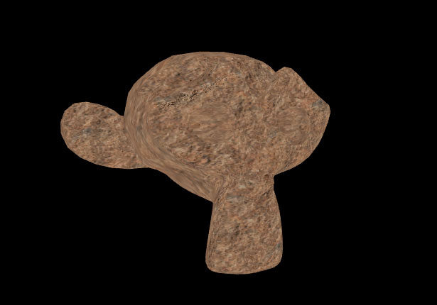
While it's more interesting that the flat coloured version, it's still not very realistic. What we are missing is some highlights and shadows.
Adding light
We can now move to the final and most interesting part of our shader – adding the light effect. We will create something called a hemispehere light, which is a simple and very nice way to create a lighting effect on a 3D object. The code below is adapted from examples in the wonderful OpenGL Shading Language book. I recommed this book to anyone who wants to learn shader programming in depth.
Here's the full code of the shader:
//#name HemisphereLight#ifdef GL_ESprecision highp float;#endif//#vertexattribute vec3 aVertexPosition;attribute vec2 aTextureCoord;attribute vec3 aVertexNormal;uniform mat4 mMatrix;uniform mat4 vMatrix;uniform mat4 pMatrix;uniform mat3 nMatrix;uniform vec3 uSkyColor;uniform vec3 uGroundColor;uniform vec3 uLightPosition;varying vec3 vColor;varying vec2 vTextureCoord;void main(void) { vTextureCoord = aTextureCoord; vec4 p = mMatrix * vec4(aVertexPosition, 1.0); gl_Position = pMatrix * vMatrix * p; vec3 n = nMatrix * aVertexNormal; vec3 lv = normalize(uLightPosition - p.xyz); float lightIntensity = dot(n, lv) * 0.5 + 0.5; vColor = mix(uGroundColor, uSkyColor, lightIntensity);}//#fragmentuniform sampler2D uColorTexture;varying vec3 vColor;varying vec2 vTextureCoord;void main(void) { vec4 tc = texture2D(uColorTexture, vTextureCoord); gl_FragColor = vec4(tc.rgb * vColor.rgb, 1.0);}Lots going on here! Let's go throught the code line by line.
attribute vec3 aVertexNormal;We already had the vertex position and texture coordinate attributes, but for light calculations we'll also need the vertex normals. aVertexNormal is a J3D built-in attribute. As you might remember, the normals are defined in our geometry file, so if we declare it here, J3D will automatically set it to the right values.
uniform mat3 nMatrix;In order to transform normals from local space in which they are defined into world space we don't use the model matrix but a special matrix called normal matrix. The normal matrix transforms the normal direction but doesn't apply translation. In J3D it is built-in and is named nMatrix.
uniform vec3 uSkyColor;uniform vec3 uGroundColor;uniform vec3 uLightPosition;These are custom uniforms that we will use to calculate the lighting. They are all three component vectors and we will be setting them in JavaScript later on.
varying vec3 vColor;We are adding another varying variable – vColor. It will hold the colour of the light for each vertex. Varying values are interpolated when passed from the vertex shader to fragment shader, so the light values will transition smoothly on the surface of our model.
vec4 p = mMatrix * vec4(aVertexPosition, 1.0);gl_Position = pMatrix * vMatrix * p;This is the same operation as we did before, but now we break it up into two steps. First we calculate the position of the vertex in world space and keep it in a variable called p. Later we transform it into the camera space and apply perspective projection to it. We will use the world position in the light calculations.
vec3 n = nMatrix * aVertexNormal;vec3 lv = normalize(uLightPosition - p.xyz);float lightIntensity = dot(n, lv) * 0.5 + 0.5;vColor = mix(uGroundColor, uSkyColor, lightIntensity);This is where the magic takes place! First we transform the normal into world space. Then we find the vector going from the vertex to where the light is (we assume it's already defined in world space). The dot function returns the so called dot product of the two vectors. The dot product of two normalised vectors is equal to the cosine of the angle between them – going from 1 if the angle is 0 to -1 if the angle is 180. The lightIntensity intensity is based on this value – the larger the angle, the smaller the intensity. Finally we use the GLSL mix function to interpolate between the sky colour, which is the colour of the light, and the ground colour, which is the colour of the shadow.
Changes in the fragment shader are minimal. We add the declaration of the vColor varying first.
Every varying variable declared in the vertex shader must be declared in the fragment shader as well, otherwise you will get a compile time error. To avoid always typing the code twice, in J3D you can put the declarations of varyings in the common section of the shader code – after the //#name declaration. That way you make sure that the declaration is included in both shaders.
gl_FragColor = vec4(tc.rgb * vColor.rgb, 1.0);Finally we multiply the colour from the texture by the light colour to compute the value for each pixel.
Before we run the code, we need to make sure that the uniforms are populated with some meaningful values. Go back to the HTML document, and just after the line where we set the texture add the following lines:
// add after the line: monkey.renderer.uColorTexture = ...monkey.renderer.uSkyColor = J3D.Color.white; monkey.renderer.uGroundColor = J3D.Color.black;Colors in J3D are defined using the J3D.Color class. There are some constants like above, but you can also creating any colour by using the constructor:
var c = J3D.Color(R, G, B, A);Values for the colour components are in range 0-1 and the last one, specyfing the alpha can be ommited. If the uniform is of type vec3, like in our case, J3D will only pass values for RGB and skip the alpha.
One last thing! We now pass the light colours but we still need to pass the light position. We can tie it to the position of the mouse, that way the light will move around the objec as we move the cursor. Go to the draw function we defined previously and just before the call to engine.render() add the following line:
monkey.renderer.uLightPosition = [mx * 10, my * -10, -5];That way the x and y position of the mouse cursor will determine the x and y position of the light source. The z position of the light source is constant. Notice that the y position is inverted. That is because screen y-axis goes from top to bottom and webgl y-axis goes in the other direction.
If everything went ok and your code is correct, you should see the monkey head textured and lit and the light should change its position as you move the mouse:

Conclusion
Writing shaders can take some time to get used to. This tutorial presents a lot of information but gives you a full overview of the process of creating shaders with J3D. J3D is designed to facilitate shader editing so that you can focus on writing GLSL code and implementing various algorithms. The OpenGL Shading Language book is a very good place to start and most of the examples can be adapted to WebGL and J3D. I hope you will have much fun creating shader effects!

The Creative Bloq team is made up of a group of art and design enthusiasts, and has changed and evolved since Creative Bloq began back in 2012. The current website team consists of eight full-time members of staff: Editor Georgia Coggan, Deputy Editor Rosie Hilder, Ecommerce Editor Beren Neale, Senior News Editor Daniel Piper, Editor, Digital Art and 3D Ian Dean, Tech Reviews Editor Erlingur Einarsson, Ecommerce Writer Beth Nicholls and Staff Writer Natalie Fear, as well as a roster of freelancers from around the world. The ImagineFX magazine team also pitch in, ensuring that content from leading digital art publication ImagineFX is represented on Creative Bloq.
