Behind the virtual lens: get to know your CG camera
VFX supervisor Denis Kozlov exposes the theory of the virtual camera to help you create faultless renders.

While there is hardly a CG image rendered without them, virtual cameras are often overlooked by the artists, who understandably prefer to focus on scene geometry, lighting and animation. A camera, with its seeming simplicity, stays behind the scenes both literally and metaphorically.
Nevertheless, it possesses some not too obvious features and properties, which can either help or hinder you during the project. I'll be addressing these things here, so that you can get to know your CG camera better.
The camera's anatomy
Anatomically, a CG camera is described by three-dimensional position and rotation coordinates (just like any other object), horizontal and vertical angles of view, and two clipping planes: near and far. Put together these properties form the view frustum, or the pyramid of vision of the notional camera.
Clipping planes are designed to optimise rendering by excluding unneeded portions of the scene, and normally have little practical significance as they are most commonly set automatically by the software.
One thing to watch for is that nothing gets unintentionally clipped off – especially when transferring a camera between applications and/or drastically changing the scale of a scene. In certain cases, you may also find the clipping planes handy to quickly slice the scene into portions based on depth for separate rendering.
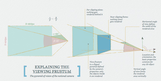
Once the position and rotation of the camera are known, it is two angles of view (horizontal and vertical) which do the best job of describing what exactly is going to be seen/rendered. The relation between them also provides us with the information about the final image's aspect ratio. (Angle or field of view abbreviate as AoV or FoV respectively.)
More often you would have one value for the angle (either horizontal or vertical), and the second one would be derived from the final image's aspect ratio, which is pretty much the same and easily convertible. We'll touch upon this and the focal length – which is another parameter describing the camera's angles – later in the article.
Daily design news, reviews, how-tos and more, as picked by the editors.
Revert from default
Every piece of software I can think of defaults to average camera angles. Whether the project allows you to set them arbitrarily or you need to match a live-action plate, leaving these values at their defaults without even considering an adjustment is ignoring an opportunity to improve the work.
Natural human field of view is a subject for a longer discussion than we have room for here, and interpretation is based on what one would define as 'seeing' and other individual factors. However, a horizontal angle of 40-60° is often considered to correspond to the useful field of view – the area in which we can distinguish objects at a glance, without moving the eyes or the head.
Therefore the default camera angles should provide a decent starting point for representing an observer, but deviating from them enables you to emphasise drama or other artistic aspects of the image, making it more interesting and expressive overall. Wide angles generally facilitate dynamism and drama while introducing distortions, whereas narrow ones allow for focusing on details and compressing the space.
Position, rotation and field of view is all you really need to know to perfectly match your notional camera with the majority of 3D editors. However, life has a tendency to make things harder, so this is where things start to get more complicated.
Matching the cameras
In the first instance, we need to check how each of the programs we're matching the cameras with measures the AoV – horizontally, vertically, both or even diagonally? Then we can just 'copy and paste' the data if the measurement is of the same type, or do a simple conversion using the image aspect ratio as a coefficient if they differ.
However, this might not work, as one of the programs you are using might rely on real-world camera parameters, like focal length and aperture size, to define the camera's FoV, which would bring us to the second point: what if you need to match your virtual camera to a real-world one?
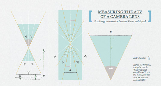
The difficulty is that it is quite hard to measure the actual angles of view for a physical camera. Because of this, to describe the zoom level in photography and cinematography we use focal length instead, which is a great convention for those who deal with real cameras daily, but makes things much less straightforward when applied to the computer graphics world. Here is a very rough description of how it relates to the angle of view (AoV).
Light passes through the lens, is focused and projected or flipped onto a film or a sensor – let's use the word 'film' for nostalgic reasons. Moving the film closer to or further away from the focal point makes different parts of the image appear sharper or softer. This is a relatively small movement in an area defined by the lens design and marked as the lens's focal length (F) – the distance from the focal point to the film.
Simple setups
Lenses with a higher focal number will have film located further away from the focal point. However, since the film has a constant width (X), the longer the lens, the narrower its angle of view will be. Actually, it is usually the lens that moves – not the film back – but that's irrelevant for our discussion.
Another thing we can change in our setup is to put the film back in front of the focal point – all the angles and ratios will stay geometrically the same, but now the setup will be simpler and correspond better to a CG camera
Knowing all this we can now convert the focal length into the angle of view. The first thing to notice is that focal length alone tells us absolutely nothing about the angle of view unless we know the film back size (or sensor size, as it is often referred to in CG).
A good thing is that lenses are usually marked with focal length which corresponds to a 35mm film. Usually is the important word here, since no-one would actually guarantee this is the case; you will simply have to check the documentation on your particular lens/camera model.
However, even with 35mm film there are issues as the actual area exposed to light (and this is the area that defines the angle) is smaller, about 24mm. You also have the additional problem that almost every DSLR camera has its own sensor size.
Errors and aberrations
As if this doesn't make things hard enough, your 3D software will probably have its own system for describing the virtual aperture size and proportions with coefficients for overscanning and rules for which dimension (width or height) is the dominant one.
Even more confusingly, you will have to interrogate all these measurements to find out which axis (horizontal or vertical) is described, and if the sizes are given in inches or millimetres. Oh, and remember that you may have to do a sum or two as well – double-checking if the tangent function uses degrees or radians, for example – and not simply trust the scripting manual.
Finally, we should be mindful that the error of such conversions is increased by the fact that with 'physical' cameras, there are always physical aberrations. The bottom line is that if you have a choice, stick to the angle of view rather than focal length when transferring your camera data between different programs.
Rendering overscan
However, if you do need to use focal length rather than the angle of view, there is a neat CG trick, which you can do. This can be used when you need to overscan – render a wider image of the same scene so that the middle part matches perfectly. This allows you to add zoom, shake or simply recompose the image in compositing, and is especially useful when using virtual camera projection techniques.
The problem is that if you were to increase the AoV, the size occupied in-frame by the original image would change in non-linear proportion. So if, for example, we double the AoV, our initial framing will not be exactly half the width or height of the new image.
The better option is to divide the focal length by two. The benefit of using the focal distance is that the picture size changes proportionally, so an object shot with a 50mm lens will look 1.5 times smaller than one shot with a 75mm lens from the same point.
So if you want to render a wider version of the image, while preserving the initial render matching pixel-to-pixel in the centre, you need to divide the focal length by the same number that you multiply the output resolution. This is a handy trick as it works in the same way in any application.
Aligning the perspective
Showing the scene from a low point, especially with a wide lens, is one way to accent its scale and significance. This is a method that's used often in architectural visualisation. However, another thing often desired in architectural visualisation renderings is to preserve the verticals, and that will only happen when the camera is pointing exactly parallel to the ground.
As a consequence, the horizon line has to coincide with the vertical centre of a frame, which results in an image that is not very good compositionally.

Unless you're using some fancy camera shader that does vertical lines compensation for you (like the one in V-Ray, for example), the way to go is to expand the vertical angle of view, render the image centred (with the camera pointing parallel to the ground plane) and then reformat (crop out the unneeded areas) in 2D. In such cases it's also worth considering rendering only a partial region of the frame to save time.
And as we're touching on perspective issues, the further the objects are away from a camera, the more of them it takes to fill up the view. This means it is often practical to use foreground objects or telephoto (narrow angle) lens to create a busy impression with fewer assets in the frame.
Nodal panning
Rotating our notional camera without changing its position mimics what is called a nodal pan in cinematography, and features no parallax changes in the resulting images – that is, all the objects keep their positions relative to each other; even the shape of the reflections don't change. This is very useful for visual effects shots, since it allows for the use of a 2D matte painting instead of a full 3D solution.
It also means that images rendered in this way can be stitched together seamlessly. However, if you try to stitch them in a straightforward manner, it won't work, which can be seen in the two frames in the example above.
The right way to do so would be to first project them onto a sphere, centred around the cameras. In a similar way, when creating a pan animation from a still frame, it is best to first project the image onto a sphere, or to at least mimic this behaviour with a distortion applied after the pan animation in 2D.
Hopefully, the aspects listed in this article will be useful in improving your artistic experience. We have been looking at the capabilities of a CG camera – which is basically a simplification of its real-life counterpart – and in the sidebar here I have listed effects that you might get with film but which would need to be added to CG shots.
Replicating these features can add a breath of life to the frame, but overdoing them can make the whole image look artificial. It's all about balance and achieving the cleanest picture you can.
Words: Denis Kozlov
Denis Kozlov is a CG generalist with 15 years' experience in the film, TV, advertising, game and education industries. He is currently working in Prague as a VFX supervisor. This article originally appeared in 3D World issue 180.

The Creative Bloq team is made up of a group of art and design enthusiasts, and has changed and evolved since Creative Bloq began back in 2012. The current website team consists of eight full-time members of staff: Editor Georgia Coggan, Deputy Editor Rosie Hilder, Ecommerce Editor Beren Neale, Senior News Editor Daniel Piper, Editor, Digital Art and 3D Ian Dean, Tech Reviews Editor Erlingur Einarsson, Ecommerce Writer Beth Nicholls and Staff Writer Natalie Fear, as well as a roster of freelancers from around the world. The ImagineFX magazine team also pitch in, ensuring that content from leading digital art publication ImagineFX is represented on Creative Bloq.
